While wasting time on youtube, time better spent on homework, one discovers the strangest things. From teenagers who build waterslides off their parents’ house to cars that climb hundreds of feet of volcanic ash in seconds, the possibilities are limitless. A couple of months ago, I discovered a video of the Russian-designed Sukhoi-30 performing at an air show. I was blown away! The maneuvers that this thing is capable of are astonishing. It is even capable of flying backwards. For the record, those near-stall speed back flips are insanely hard to do perform according to flight dynamics, but that's another topic. I immediately started looking for information on the plane and found that most of its flight abilities were granted by the use of thrust vectoring control (TVC) nozzles.
Any engine that changes the direction of the jets’ exhaust from its normally axial flow can be considered thrust vectored. Thrust reversing, 2D and 3D nozzles are all examples of these specialized engines. Nozzles classified as '2D' can alter thrust in two directions, most commonly in the vertical plane, providing enhanced pitch control and in some cases, vertical landing and takeoff capabilities. '3D' nozzles provide the same vertical vectoring found in 2D but also offer vectoring in the horizontal plane. This enhances yaw control, advantageous during post-stall maneuvers. By vectoring the thrust leaving the engine, a moment is created on the aircraft that otherwise would not exist. Newton's second law takes over from there. This added force enables much faster changes in direction and maneuverability below stall speeds, not possible with conventional mechanical control surfaces.
Vectored thrust nozzles come in many shapes and sizes, but by far the most common form of thrust vectoring is thrust reversing (TR). Reversing nozzles are standard on almost every commercial jet liner produced. Commercial airliners use reverse thrust in addition to heavy-duty brakes, both mechanical and air spoilers, to reduce the length of required landing roll (distance). First installed on the Boeing 707 and the De Havilland Comet in the 1950s in order to operate from the commercial runways of the day. Other planes airlines were operating included the Douglas DC-3, which needed about 2600 feet of runway to land and the Lockheed Constellation, which needed about 3400 feet. While most thrust reversing is accomplished on the ground, some planes can apply TR in-flight, this enables rapid descents in altitude without over stressing the aircraft structures. NASA uses a highly modified Gulfstream to train space shuttle pilots in landing maneuvers. Because of the high angle of attack required to simulate a shuttle landing, the thrust reversers in the engine are enabled, limiting the airspeed that would ordinarily lead to failures of the airframe and controls (hmmmm, flutter and dive flaps, the topics are endless!).
Thrust reversing works by reversing the thrust of the jet engine. This includes the ‘hot’ exhaust gases or the ‘cold’ fan thrust. Some aircraft utilize reversers on both of the flows, enhancing the amount of thrust that actually changes direction, therefore stopping sooner. Old Boeing 747s and today’s C-17 Globemaster III (look the vents are open!!) turbofan transport are examples. Reversing engines come in three varieties with each accomplishing the direction change in their own way.
The first type uses internal ‘clamshell’ doors that close and evacuate the gases through built-in vents. The system is usually hydraulically activated. This method benefits from reduced drag from external components but suffers from the design in the same way. Since the doors are internal, maintenance time is longer. Pilots and crew cannot visually inspect the doors easily either, as all components are internal.
The second system uses external, hydraulic actuators that move buckets into the exhaust flow. Though increasing the amount of drag and engine has while in flight, the actuators are the easiest to service and make quick visual inspections of mechanisms possible. If a problem does develop; the entire system is essentially external to the engine, allowing a quick turnaround time from the hangar to the airfield. One can clearly see when this system is activated, as the huge buckets folding out behind an engine are evident.
The third system is the most common on today’s large, turbofan engines and usually only direct the ‘cold’ fan thrust. Once activated, a large inner blocker door is levered into position, at the same time outer vents in the engine nacelle are opening. The inner door directs the flow through the open vents in the cowling. This system is also apparent once activated, as the engine nacelle vents will be clearly visible. Since most of the thrust comes from the fan of a turbofan engine, a reversing device on the jet exhaust would not provide a great enough performance benefit for the weight it would add per engine. Here's an interesting fact- early B-747 models were equipped with both hot and cold reversers but most of the hot reversers were disabled, as they were high maintenance and seldom performed correctly. An exception would be Boeing’s C-17 military transport, which relies on both forms of vectoring due to the extreme takeoff and landing demands in a combat environment.
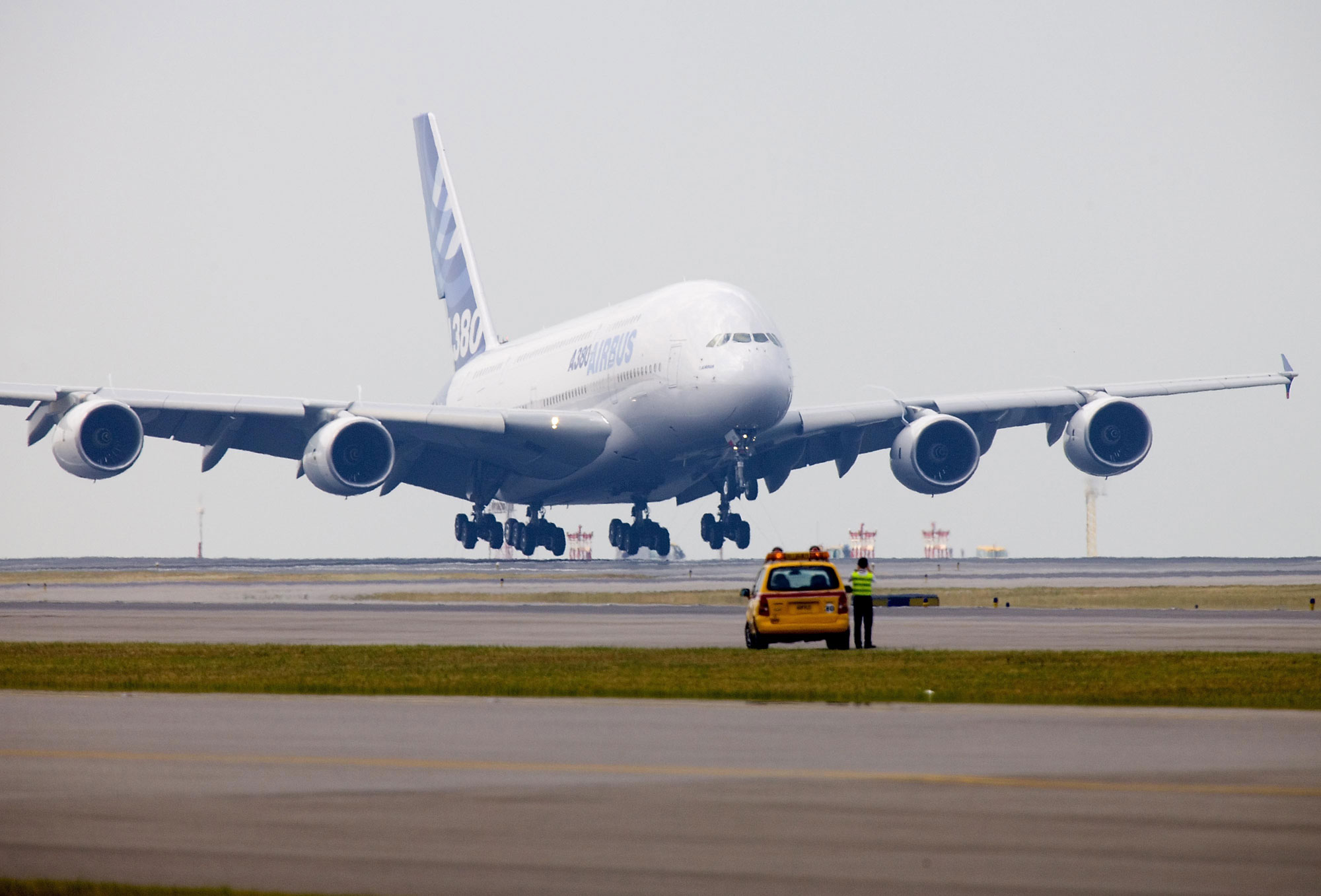
It may be surprising to know that the Federal Aviation Administration (FAA) does not allow the use of thrust reversing when calculating landing rolls for aircraft. Actually, the Administration states that thrust reversers should only be used to offset any other variables that could significantly increase required landing distances, such as weather conditions, aircraft loading or runway debris. Most people are shocked to learn that only the two inboard engines on Airbus’ giant transport, the A380, have reverse thrust capabilities.
By far the most exciting applications of thrust vectoring come from military aircraft. The extreme demands and operating conditions of aircraft in combat warrant the use of advanced technologies to gain any advantage over the enemy. Thrust reversing is nothing special compared to the technologies incorporated in some fighters today and actually is an outdated technology. Vectoring can be accomplished by mechanical means, such as changing the nozzle shape, or by more advanced, fluidic means.
The easiest, heaviest and simplest method is changing the angle of the motor. Using brute force and rotating the entire engine, the thrust can be directed in the appropriate direction. This method is employed on Bell’s V-22 Osprey tilt-rotor aircraft. The aircraft was developed as a vertical/short take off and landing (V/STOL) transport that could function like a helicopter but fly like a plane. This allows the Osprey to have all the advantages of helicopter maneuverability with the flight capabilities of fixed-wing aircraft.
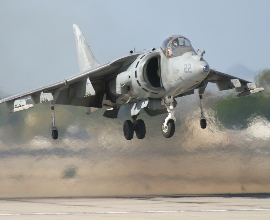
In fighter aircraft, rotating the engine is not a feasible option. Fortunately, only the exhaust coming from the nozzle of the engine needs to be directed for any performance gain. Probably the more elementary method is that utilized by the Hawker AV-8 Harrier. This V/STOL attack aircraft was the first of its kind when it was developed in the late 1960s and has been updated through the years to increase its performance. One Rolls Royce turbofan engine powers the Harrier. The engine has two directional nozzles that provide 2D vectoring; one just behind the fan to divert cold flow and one at the rear of the engine to direct the jet exhaust. To provide rotational stability, small air puffers in the nose, wing tips and tail boom of the aircraft fire jets of air laterally. Flight tests are currently being performed on the newest V/STOL jet, Lockheed’s F-35 JSF. The whole rear nozzle on the jet deflects downward and, with the assistance of a fixed vertical fan behind the cockpit, allows vertical maneuvering.
Similarly, Lockheed’s F-22 Raptor utilizes a 2D systems, but only functions on the exhaust flow. The two Pratt & Whitney F119 turbofans have the ability to vertically vector 70,000 lbs of thrust ±20° from center. This provides the pilot with a beneficial moment about the lateral axis of the aircraft, enabling very quick pitch response and the limited ability to maneuver in post-stall conditions.
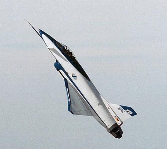
The ultimate in thrust vectoring performance comes from the implementation of 3D nozzles. These enhance yaw control in addition to aiding in pitch rotation. There are a few ways to do this. NASA’s X-31 and F-16 MATV projects used paddles to direct the exhaust. 3D TVC nozzles are also found on the Russian Sukhoi Su-30 and Mikoyan-Gurevich MiG-35 series of air-superiority fighters. The Su-30 uses a huge ball-joint connection between the nozzle and the engine. The nozzle rotates with the aid of hydraulic actuators. This system can be a bit bulky and a slimmer alternative is utilized on the MiG-35, F-15 ACTIVE and the F-16 MATV. This system overlaps flaps of the nozzle surface so it looks like the pedals of a flower. Internal hydraulic actuators push and pull certain ‘pedals’ to deform the nozzle. This system is the cleanest mechanical design, aerodynamically speaking, and also reduces the nozzles’ radar signature.
TVC can also be achieved by applying principles of fluid flow to the exhaust. Researchers have discovered that by introducing a jet of fluid into the exiting jet exhaust will cause the flow to change direction. By capitalizing on the properties of shockwaves, jets of air can be introduced into exhaust flow. As the jet enters the exhaust, an oblique shock wave is formed, deflecting exiting exhaust gas. Designers can also capitalize on the Coanda Effect in which a fluid tends to follow a curved surface. This effect is also known as boundary layer attachment. By introducing co-flowing and counter-flowing fluids into the exhaust along a coanda surface, the flow will change direction, as it wants to attach to the curved surfaces .
Fluid vectoring has some advantages over TVC by mechanical means. Although a mechanical thrust vectoring system is effective, it can be heavy, complex, difficult to integrate and aerodynamically inefficient. A fluidic thrust vectoring system has the advantage of being lightweight, simple, inexpensive and free from moving parts (fixed geometry), and can be potentially implemented with minimal aircraft observability penalty. (cough UAVs cough cough)
Super-maneuverable aircraft can’t just rely on advanced engine vectoring to push the envelopes of performance. Variable intakes that operate at extreme angles of attack must feed air to the high-performance engines in order for any TVC technology to be useful. Also, with today’s advances in fly-by-wire control systems, the computer must be able to calculate a situation based on the instantaneous characteristics of the aircraft. One method currently in development at NASA’s Dryden Research Center (please hire me! I don't care if I have to live in a desert!) is a method of determining airspeed without the use of a pitot-static tube. Dubbed Flush Air Data Systems, the device eliminates the need of an external measuring device and performs through high AOA maneuvers. By eliminating external pitot tubes, a plane can further reduce it’s radar signature, enhancing stealth properties. This system is currently being developed on NASA high AOA research platforms on a McDonnell Douglas F-18 fitted with TVC nozzles and Rockwell’s X-31 experimental plane.
TVC’s use in V/STOL aircraft is unparalleled and will no doubt continue to be a home for most of the technology. Though the technology is a huge advancement in aircraft maneuverability however, I do not believe it holds a place in manned fighter aircraft. Sure, its ability allows for phenomenal air show demonstrations and in extreme in-flight maneuverability, but the days of the close-combat dogfight are becoming history. I know, I know, that’s what McDonnell Douglas said when they designed the F-4 without a gun back in the 1960s but it’s true. With current avionics and weapon systems, targets are now acquired and fired upon before a bogey is even located visually. As of yet, unmanned aircraft have not engaged air-to-air targets but if they ever do make the leap, an unmanned aircraft will always outperform a manned one, due the limits of the human body. TVC does offer another layer of safety for those planes it is installed on. The technology could potentially allow a damaged plane to limp back to base using thrust control to assist control surfaces and its shocking ability to keep a plane in control, even during stall conditions could be useful if a plane ever entered into an ‘uncontrollable’ flat spin or other usually catastrophic situation.
Thrust vectoring is used to enhance the performance of a number of aircraft in service today. It has advanced greatly since its first applications on the commercial airliners of the jet age. TVC has allowed for aircraft that are able to land in record distances, planes that land like helicopters and epic air show demonstrations. Though future applications of TVC are still unknown to the public, there is no doubt that the advances will continue to push the envelope further than imagined.
_ttk3
----------------
Now playing: Firewall - Sincere
via FoxyTunes

 THE rally bug has bitten me. I guess it's a common species, attracted to bored engineers and especially harmful if said engineers congregate in small groups. [I have also heard reports that the humid warmth of machine shops also provide ample breeding conditions] So I guess it is no surprise that I find myself frantically trying to track down set of snow tires for this weekends road rally.
 in the long run. I'm picking up a set of used snows on Friday and getting them mounted up. I rewired my fog lights, removing all safety items and relays, to get them to operate again. I also replaced my head light bulbs, with a high octane pair of Osram bulbs, straight off the boat from Germany. The picture is really only good for cosmetic comparison, but the performance is unbelievable! More info on these beasts over at honda-tech. I secured a co-driver, too. A fellow ME, so the math part shouldn't be a problem. He even has one road rally navigation under his belt, though that was in an AWD Legacy, the civic may prove to be a sub par vehicle for this....